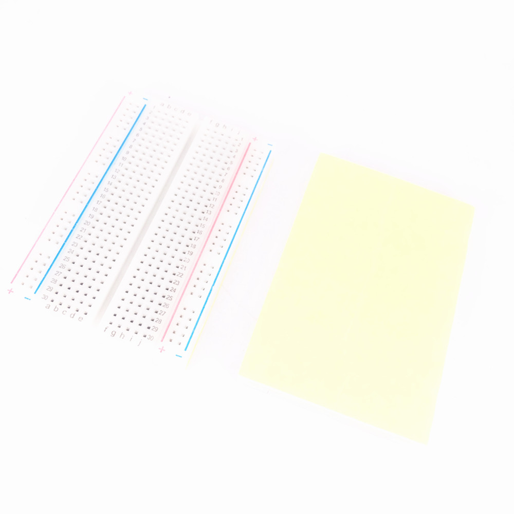
A breadboard is a grid of sockets for developing electronic circuits and microcontroller projects, composed of conductive strips beneath the nonconductive cover. Because it is solderless, it's useful in prototyping, but more susceptible to falling apart when handled roughly.
The main grid, which is 10 columns wide and labelled a through j, has connections across every row, connecting a through e of every row, and f through j of every row. On most boards, the 4 columns bracketing the main grid are all connected across every column, from the top of the board all the way to the bottom. These 4 columns are traditionally used as power and ground lines.

Large
The large breadboard is used when you need to make a lot of connections. Maybe you have a lot of parts with complicated chip wiring set-ups, or you are constructing a project where it's imperative to have all the wiring in a central location for personal legibility, as opposed to in several smaller breadboards dispersed throughout.
As a caveat, some large boards held in the physical computing lab have the 4 external columns split in half and are therefore not conductive all the way down.
Medium
The medium breadboard is fairly versatile and probably the most commonly used size of breadboard in the physical computing lab. You can place multiple of them at various locations throughout the project and it won't get too clunky, yet a single one's still large enough to house pretty much all the connections you'd need on most projects.
Small
The small breadboard in particular is used when you need to make a very limited number of connections. Maybe you just don't need to connect a whole lot of parts, or you are constructing a project whose dimensional constraints demand that you use small breadboards placed at various important locations.
The small boards held in the physical computing lab only have the row connections, and not the bracketing power/ground columns commonly found in other breadboards.
Uno compatible breadboard shield
Breadboard shields reduce the need for numerous long jumper wires by situating a breadboard on top of the Uno for quicker prototyping. The breadboard sits on a grid of exposed conductive material, including two pairs of ground and 5V lines. The digital and analog input/output pins bracket the breadboard, allowing for swift, small connections.

| Part | Location | On floor | Backstock | |
|---|---|---|---|---|
| 2104 | Grid of sockets for developing electronic circuits and microcontroller projects, composed of conductive strips beneath the nonconductive cover | Wiring 4 | 11 | 93 |
| 2106 | Grid of sockets for developing electronic circuits and microcontroller projects, composed of conductive strips beneath the nonconductive cover | Wiring 4 | 25 | 118 |
| 2108 | Grid of sockets for developing electronic circuits and microcontroller projects, composed of conductive strips beneath the nonconductive cover | Wiring 4 | 90 | 192 |
| 4002 | Provides a convenient, compact area for a breadboard circuit directly plugged in to the top of the Arduino Uno. | — | — | 0 |