An H-bridge is an electronic circuit that switches the polarity of a voltage applied to a load. These circuits are often used in robotics and other applications to allow DC motors to run forwards or backwards. (Adapted from Wikipedia)
The lab stocks two: a DRV8833-based dual motor driver, and a generic H-bridge module.
DRV8833 dual motor driver
The DRV8833 dual motor driver can be used for bidirectional control of two brushed DC motors at 2.7V to 10.8V.

Note that "GPIO" above means "general purpose input/output" and corresponds to digital pins on the Arduino.
All GND pins must be connected to ground, and VIN (powering the motors) takes 2.7V to 10.8V. The leads of the DC motors must be connected to their output pins (motor A has both leads to motor A output pins, and the same applies to motor B). All 4 signal pins (BIN1, BIN2, AIN2, AIN1) must be connected to digital pins on the Arduino. These are a bit trickier, but they dictate the polarity of voltage and therefore the direction of rotation. The xIN1 and xIN2 pins must be a HIGH/LOW pair for the motor to spin, supplying HIGH to both or LOW to both won't make the motor spin; but having xIN1 be HIGH and xIN2 be LOW will make the motor spin in the opposite direction than if xIN2 was HIGH and xIN1 was LOW.

This monster of a diagram actually isn't too bad when you take a closer look. The pins in the upper right and lower left corners (logic and motor power) must always have power for the circuit to work (they supply power to the internal chip computer and the motors, respectively). The enable pins (upper left and lower right) are also connected to power to allow the motors to go on (if motor 1's enable is LOW, it won't spin no matter what, and the same applies to motor 2).
The leads of the DC motors must be connected to their output pins (motor 1 has both leads to motor 1 output pins, and the same applies to motor 2). All 4 signal pins (motor 1 A, motor 1 B, motor 2 A, and motor 2 B) must be connected to digital output pins on the Arduino. These are a bit trickier, but they dictate the polarity of voltage and therefore the direction of rotation. The A and B pins must be a HIGH/LOW pair for the motor to spin, supplying HIGH to both or LOW to both won't make the motor spin; but having A be HIGH and B be LOW will make the motor spin in the opposite direction than if B was HIGH and A was LOW.
Here is some simple sample code using wiring shown in the above schematic to move the motors in alternating directions:
/*
  Simple H-bridge driver demo

  Drives two motors in alternating directions

  Pin mapping:

  Arduino pin | role  | description
  ----------- | ----- | ------------
  2             output  motor 2 signal A
  3             output  motor 2 signal B
  7             output  motor 1 signal B
  12            output  motor 1 signal A

  Released to the public domain by the author

  Robert Zacharias, rzachari@andrew.cmu.edu
  Sep. 2025
*/

// set up pin numbers
const int MOTOR2APIN = 2,
          MOTOR2BPIN = 3,
          MOTOR1BPIN = 7,
          MOTOR1APIN = 12;

void setup() {
  pinMode(MOTOR2APIN, OUTPUT);
  pinMode(MOTOR2BPIN, OUTPUT);
  pinMode(MOTOR1BPIN, OUTPUT);
  pinMode(MOTOR1APIN, OUTPUT);
}

void loop() {
  // drive motor 1 in some direction
  digitalWrite(MOTOR1APIN, HIGH);
  digitalWrite(MOTOR1BPIN, LOW);
  // drive motor 2 in opposite direction
  digitalWrite(MOTOR2APIN, LOW);
  digitalWrite(MOTOR2BPIN, HIGH);

  delay(2000); // do the above for two seconds

  // drive motor 1 in different direction from before
  digitalWrite(MOTOR1APIN, LOW);
  digitalWrite(MOTOR1BPIN, HIGH);
  // drive motor 2 in different direction from before
  digitalWrite(MOTOR2APIN, HIGH);
  digitalWrite(MOTOR2BPIN, LOW);

  delay(2000); // do the above for two seconds

  // stop both motors by turning all outputs low
  digitalWrite(MOTOR1APIN, LOW);
  digitalWrite(MOTOR1BPIN, LOW);
  digitalWrite(MOTOR2APIN, LOW);
  digitalWrite(MOTOR2BPIN, LOW);

  delay(1000); // do the above for one second
}
| Part | Location | On floor | Backstock | |
|---|---|---|---|---|
| 0482 | Able to drive two motors both clockwise and counterclockwise | Special Parts Cabinet | 2 | 0 |
| 0483 | motor driver, H-bridge, 1.7A continuous (2.5A peak), 1.8 22V, MP6550 | Output: Movement | 0 | 0 |
| 0485 | motor driver, H-bridge, dual driver, 1A continuous (3A peak) per channel, 4.5–13.5V, TB6612FNG | Output: Movement | 15 | 16 |
| 0486 | motor driver, H-bridge, 9A continuous (30A peak) @ 5.5 16V, VNH3SP30 carrier | Lending | 4 | 0 |
| 0488 | motor driver, dual H bridge, 1.2A continuous (1.5A peak) per channel, 0–11V, DRV8835 carrier | Output: Movement | 5 | 19 |
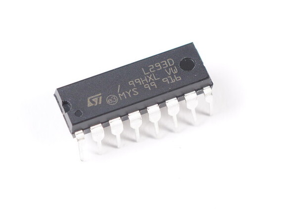
| 1256 | motor driver, H-bridge, 4.5V 36V supply and load, 1A output, bipolar, 16-DIP, L293NE | Output: Movement | 13 | 0 |
| 1258 | Receives motion instructions from the Arduino, and allows 2 motors to rotate both ways. | Output: Movement | 34 | 0 |